From Tim's website
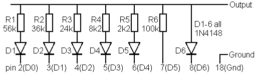
Revision as of 22:25, 20 February 2010 by Tim (talk | contribs) (Circuit diagram for the Minidisc Control Lead. The resistor network allows a digitally controlled load to be applied to the output.)
No higher resolution available.
Minidisc_Control_Lead_Circuit.png (509 × 148 pixels, file size: 2 KB, MIME type: image/png)
Circuit diagram for the Minidisc Control Lead. The resistor network allows a digitally controlled load to be applied to the output.
File history
Click on a date/time to view the file as it appeared at that time.
| Date/Time | Thumbnail | Dimensions | User | Comment | |
|---|---|---|---|---|---|
| current | 22:25, 20 February 2010 | 509 × 148 (2 KB) | Tim (talk | contribs) | Circuit diagram for the Minidisc Control Lead. The resistor network allows a digitally controlled load to be applied to the output. |
You cannot overwrite this file.
File usage
The following page uses this file: